Are Switchboards Water Proof?

Switchboards are not typically designed to be waterproof. However, they are constructed to provide a level of protection against environmental elements, including moisture, dust, and debris. The degree of protection against moisture depends on the switchboard’s enclosure rating and the environment where it is installed

Here are some key points regarding the waterproofing or moisture protection of switchboards:

Enclosure Ratings:

Switchboards are often in enclosures made of metal, such as steel or aluminium, or non-metallic materials like plastic or fiberglass. The enclosure’s rating, specified by standards such as the International Electrotechnical Commission (IEC) 60529 standard, and the AS 60529: 2004 (R2018), indicates the level of protection against environmental factors. Enclosure ratings such as IP (Ingress Protection) ratings, provide information about the switchboard’s resistance to moisture, dust, and other contaminants. For example, an IP65 rating means the switchboard is dust-tight and protected against water jets.

Moisture Protection Features:

Gasket Seals: Many switchboard enclosures have gasket seals around doors, panels, and openings to prevent water or moisture from entering the interior.

Cable Entry Seals: Seals, glands and gland plates provide a watertight seal around cable entry points to prevent water ingress along cables.

Drainage: Some switchboards may have built-in drainage systems or vents to allow any moisture that does enter the enclosure to drain out safely.

Installation Environment:

The installation environment plays a significant role in determining the moisture protection required for a switchboard. For example, switchboards installed outdoors or in damp locations may need higher waterproofing levels than switchboards installed indoors in dry environments. Hazardous or corrosive environments may require additional protective measures, such as corrosion-resistant coatings or materials.

Maintenance and Inspection:

Regular maintenance and inspection of switchboards are essential to ensure that seals, gaskets, and protective features remain intact and effective in preventing moisture ingress. Any signs of water intrusion, such as condensation inside the enclosure or water damage to components, should be promptly addressed to prevent damage and ensure electrical safety.

In conclusion, while switchboards are not inherently waterproof, they are designed with protective features and enclosure ratings to provide a certain level of moisture resistance. Proper installation, maintenance, and adherence to environmental guidelines are key to ensuring the switchboard’s protection against moisture and maintaining electrical safety.

Are Switchboards Fire Proof ?

Switchboards are typically designed and constructed to provide a level of fire resistance. They aim to mitigate the risks associated with electrical fires. However, it’s important to understand that switchboards are not inherently fireproof. Instead, they meet fire safety standards and include features that reduce fire incidents and limit their spread.

Key points regarding the fire resistance of switchboards:

Enclosure Materials:

Switchboards are often in enclosures of fire-resistant materials such as steel or other metal alloys. These materials have good fire-resistant properties and can withstand high temperatures without deforming or contributing to fire propagation. Non-metallic enclosures of fire-retardant plastics or fiberglass may also be used, especially when weight reduction or chemical resistance is important.

Fire-Rated Components:

Components within the switchboard, such as circuit breakers, switches, busbars, and wiring, may be designed to meet specific fire-resistance standards and certifications. Fire-rated circuit breakers and switches are designed to operate safely under high temperatures and to minimise the risk of electrical faults that could lead to fires.

Ventilation and Heat Dissipation:

Proper ventilation design in switchboard enclosures helps dissipate heat generated by electrical components. This prevents overheating, which can be a precursor to electrical fires. Ventilation openings also prevent the ingress of dust, debris, and foreign objects that could contribute to fire hazards.

Compliance with Standards:

Switchboards are designed, manufactured, and installed according to relevant safety standards and regulations, such as the International Electrotechnical Commission (IEC) standards,  In Australia AS/NZ 61439, and local building codes. These standards specify requirements for fire resistance, electrical safety, insulation materials, component ratings, and installation practices to reduce fire risks in electrical systems.

Installation and Maintenance:

Proper installation, maintenance, and regular inspections of switchboards are essential for fire safety. This includes ensuring that electrical connections are secure, and components are rated for their intended use. It also involves addressing any signs of overheating or wear. Fire prevention measures, such as using fire-retardant cable insulation, maintaining adequate clearances around switchboards, and following safe wiring practices, also contribute to fire safety.

While switchboards have fire-resistant features and withstand certain heat and fire exposure levels, they are not completely fireproof. It’s important to adhere to safety guidelines, follow best practices, and implement fire prevention measures to minimise fire risks in electrical installations.

The Role and Importance of Main Switches in Switchboards

Switchboards are fundamental components in electrical systems, acting as central hubs for power distribution and control. However, there’s often confusion about whether a switchboard requires a main switch and its purpose within the electrical setup. 

What is a Main Switch?

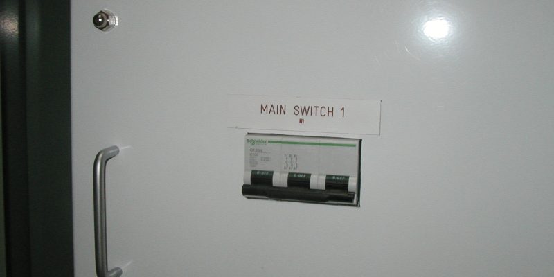
main switch, or a main circuit breaker, is a vital component in an electrical switchboard. It serves as the primary control point for disconnecting power from the entire electrical system, effectively isolating the switchboard and all connected circuits from the power source. 

Aspects of a main switch:

Disconnecting Power: The main switch is designed to disconnect the power supply to the switchboard and its associated circuits. It acts as a master control device that turns off electrical power in case of emergencies, maintenance, or safety shutdowns.

Safety Function: One of the primary functions of a main switch is to enhance electrical safety. By providing a means to isolate power locally, the main switch allows for safe maintenance, repairs, or inspections of electrical equipment without the risk of electrical shocks or hazards.

Compliance with Regulations: Many electrical codes and standards, such as the Australian and New Zealand Standards (AS/NZ 3000), mandate the installation of a main switch in switchboards. This requirement ensures compliance with safety regulations and facilitates the safe operation and maintenance of electrical systems.

Emergency Response: In emergencies, such as fires or electrical faults, the main switch enables quick and efficient power shutdown to prevent further damage, minimize risks, and facilitate emergency response efforts.

Does a Switchboard Need a Main Switch?

The necessity of a main switch in a switchboard depends on several factors, including the size of the electrical installation, the presence of sub-switchboards or distribution panels, and regulatory requirements. 

Considerations regarding the need for a main switch:

Single Switchboard Setup: In a small-scale electrical installation with only one switchboard serving as the main distribution point, a main switch is typically required. It provides essential safety features and control capabilities for the entire system.

Multiple Switchboards or Distribution Panels: In larger installations with multiple switchboards or distribution panels, each switchboard may have an individual main switch. This decentralised approach allows for more granular control and isolation of specific circuits or sections within the electrical system.

Regulatory Compliance: Compliance with electrical codes and standards often dictates installing a main switch in switchboards to ensure adherence to safety requirements and industry best practices.

Safety and Maintenance: Even if not mandated by regulations, installing a main switch in a switchboard enhances safety, facilitates maintenance procedures, and provides emergency shutdown capabilities, making it a valuable addition to any electrical system.

In conclusion, a main switch plays a critical role in switchboards by providing a means to disconnect power from the entire electrical system. While the necessity of a main switch may vary based on installation size, regulatory requirements, and safety considerations, its presence significantly enhances electrical safety, enables efficient maintenance procedures, and ensures compliance with industry standards. Whether it’s a single switchboard setup or a complex electrical installation with multiple switchboards, incorporating a main switch is a proactive measure contributing to the electrical system’s reliability, safety, and functionality. 

Metering Devices In Switchboards: Roles And Uses

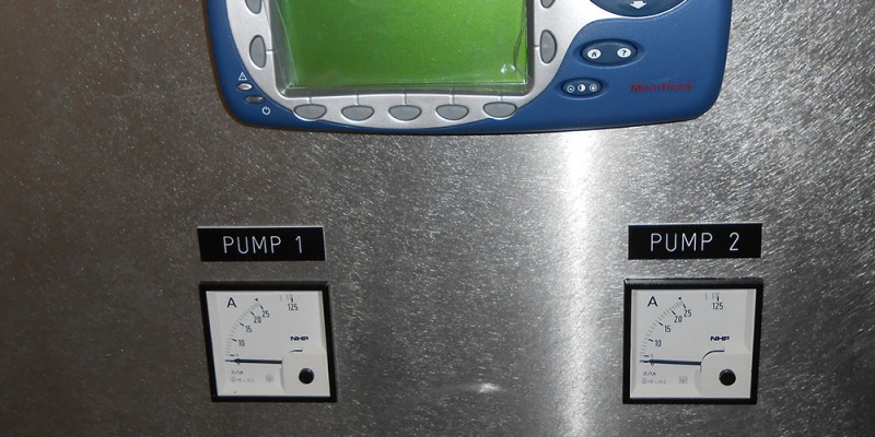
Metering devices, commonly known as electrical meters, are instruments designed to measure and display various parameters of electrical power. These parameters include voltage, current, power consumption, power factor, frequency, and energy usage. The primary purpose of these devices is to monitor and record electrical energy consumption, ensuring that electrical systems operate efficiently and within specified limits.

Types of Metering Devices

  1. Analog Meters: Analog meters are traditional meters that use a needle and dial to display readings. While they are still in use, they are gradually being phased out in favour of more modern alternatives.
  2. Digital Meters: These provide a digital readout of electrical parameters. They are more accurate than analogue meters and can display multiple parameters simultaneously.
  3. Smart Meters: These are advanced digital meters with communication capabilities, allowing for remote monitoring and data analysis. They are integral to modern smart grid systems.
  4. Power Quality Meters: These specialised meters measure parameters that affect the quality of electrical power, such as harmonics, transients, and power factors.

Role of Metering Devices in Electrical Switchboards

An electrical switchboard is a crucial component of an electrical distribution system, responsible for dividing the electrical power feed into subsidiary circuits while providing protection and control. Here’s how metering devices integrate into this setup:

1. Monitoring and Management 

Metering devices installed on switchboards continuously monitor electrical parameters. This monitoring helps in:

  • Load Management: By keeping track of the load on different circuits, metering devices help balance the load and prevent overloads.
  • Energy Consumption Tracking: Accurate measurement of energy usage helps in energy management, cost allocation, and identifying areas for energy savings.
  • Preventive Maintenance: Continuous monitoring allows for the early detection of anomalies, enabling preventive maintenance and reducing downtime.

2. Safety and Compliance

Electrical systems must adhere to various safety standards and regulations. Metering devices help ensure compliance by:

  • Recording Power Quality: Poor power quality can damage equipment and lead to inefficiencies. Power quality meters help in identifying and rectifying such issues.
  • Event Logging: Many modern meters can log events like power surges, dips, and outages. This data is crucial for troubleshooting and maintaining system integrity.
  • Regulatory Compliance: Accurate metering is often a regulatory requirement, especially in commercial and industrial setups. Compliance with these regulations helps avoid penalties and ensures safety.

3. Data Analysis and Optimization

Smart meters and digital meters equipped with communication capabilities provide valuable data that can be used for:

  • Trend Analysis: Analysing consumption patterns over time can lead to better demand forecasting and more efficient energy procurement.
  • Operational Efficiency: Detailed data helps in identifying inefficient equipment and processes, enabling targeted improvements.
  • Integration with Energy Management Systems: Metering devices can integrate with building management systems (BMS) and energy management systems (EMS), providing real-time data for optimized control and automation.

 Metering devices are crucial in modern electrical systems,  ensuring efficiency, safety, and compliance. Integrated into electrical switchboards, they provide the data and insights needed to manage electrical power effectively. As technology advances, these devices become even more sophisticated, offering enhanced monitoring, analysis, and control capabilities, thus paving the way for smarter and more resilient electrical grids.

What Is A Busbar And What Is It’s Purpose?

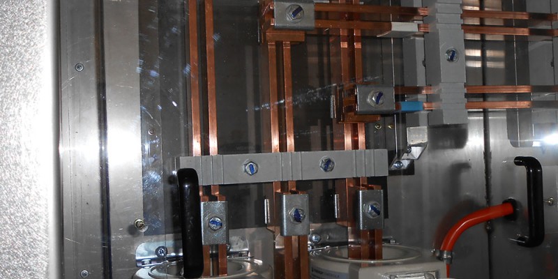
A busbar is a conductive metal bar used in switchboards and electrical distribution systems to distribute electrical power from one source to multiple circuits or loads. It is a common connection point for electrical conductors, allowing for efficient and organised power distribution within a switchboard.

What is a busbar and what function does it serve in a switchboard?

Construction and Design:

Material: Busbars are typically made of copper or aluminium due to their excellent electrical conductivity and mechanical properties. Copper is preferred for its superior conductivity, while aluminium is chosen for its lighter weight and cost-effectiveness.

Shape and Size: Busbars can vary in shape and size depending on the current carrying capacity and specific application requirements. They are often flat bars with rectangular or rounded cross-sections.

Functionality:

Power Distribution: The primary function of a busbar in a switchboard is to distribute electrical power from a main source (such as a transformer or generator) to multiple branch circuits or electrical loads.

Connection Point: Busbars serve as connection points for incoming and outgoing electrical conductors, including cables, wires, circuit breakers, switches, and other components within the switchboard.

Current Carrying Capacity: Busbars are designed to handle high currents safely and efficiently, minimising voltage drops and heat generation during power distribution.

Advantages:

Efficiency: Busbars provide a highly efficient method of power distribution compared to individual wiring for each circuit. They reduce wiring complexity, save space, and improve the overall organization of electrical connections within the switchboard.

Flexibility: Busbars offer flexibility in adding or modifying circuits within the switchboard. New circuits or components can easily connect to the busbar without extensive rewiring.

Maintenance: Busbars simplify maintenance and troublesome tasks by providing easy access to electrical connections and facilitating quick identification of circuits.

Types of Busbars:

Main Busbars: These busbars carry power from the main source to distribution points within the switchboard.

Distribution Busbars: These busbars branch off from the main busbars to distribute power to individual circuits or sections of the switchboard.

Earth (Ground) Busbars: Dedicated busbars for grounding conductors to ensure electrical safety and proper grounding of the switchboard.

In summary, busbars are crucial in efficiently distributing electrical power throughout switchboards, as they provide connection points for electrical conductors, and improve the overall functionality and organisation of electrical systems. It is an essential component that enhances switchboards and electrical installations’ reliability, safety, and performance.


Miniature Circuit Breaker Curves: Types and Applications

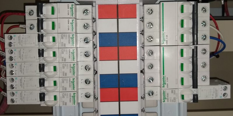
Miniature Circuit Breakers (MCBs) are used in electrical systems to protect against overcurrents and short circuits. They come in various types, each distinguished by a curve that indicates its tripping characteristics. These curves play a vital role in ensuring the safety and proper functioning of electrical installations. 

The four types of MCB curves include:

  1. B Curve: Resistive Circuits

    It trips between 3 and 5 times the rated current, making it suitable for protecting circuits with moderate inrush currents. Typical applications include control wiring and lighting circuits as they often use B curve MCBs because they provide a good balance between sensitivity and tolerance for transient loads.

  2. C Curve: The Allrounder, Inductive Loads, Most Common MCB Used In Australia

    The C curve is for circuits with higher inrush currents, for example, medium inductive loads, lighting, and GPO circuits. These MCBs trip at 5 to 10 times their rated current, offering robust protection against short circuits and sustained overloads commonly encountered in residential and commercial/industrial settings. 

  3. D Curve: High Inrush, such as motors and Industrial Applications

    D curve MCBs are for the more demanding environments, where extremely high inrush currents are expected. High inductive and capacitive loads, motors, and transformers. They trip at 10 to 20 times their rated current, providing enhanced protection for critical equipment and circuits in industrial plants, manufacturing facilities, and high-powered machinery. These MCBs are less common in residential settings but are indispensable in ensuring safety and reliability in industrial operations.

  4. K Curve: Specific Applications

    The K curve is for specialised applications requiring precise coordination with other protective devices, such as fuses or relays. They offer a unique tripping characteristic 10-14 times their rated current, that suits industrial processes and installations where coordination and selectivity are paramount. K curve MCBs are not as commonly used as B, C, or D curves but are critical in specific engineering designs.

Choosing the right curve for an MCB depends on several factors, including the type of load, the magnitude of inrush currents, and the overall electrical system’s requirements. It’s essential to consult with electrical engineers or professionals to determine the most suitable MCB curve for a particular application.

In conclusion, miniature circuit breaker curves play a crucial role in safeguarding electrical systems against overcurrents and short circuits. Understanding the differences between B, C, D, and K curves enables efficient selection and installation of MCBs tailored to specific operational needs, ensuring safety, reliability, and optimal performance.

What Does A Circuit Breaker Do In A Switchboard?

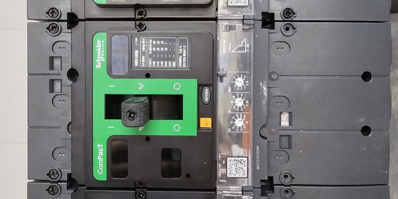
A circuit breaker is an electrical device used in switchboards and electrical systems to protect circuits and equipment from overloads, short circuits, and other electrical faults. It acts as a safety mechanism by automatically interrupting the flow of electrical current when abnormal conditions are detected, thereby preventing damage to the circuit and reducing the risk of electrical hazards such as fires or equipment damage.

Here’s how a circuit breaker works and what it does in a switchboard:

Detection of Electrical Faults:

When an electrical current flows through a circuit, the circuit breaker continuously monitors the current level. It is designed to operate within a specified current range known as its rated current or current-carrying capacity.

If the current exceeds the rated capacity due to an overload (e.g. too many devices connected to the circuit) or a short circuit (e.g. a direct path between live and neutral wires or earth), the circuit breaker detects the fault and trips.

Trip Mechanism Activation:

When an overload or short circuit occurs, the circuit breaker’s trip mechanism is activated. The trip mechanism can be electronic, thermal, magnetic, or a combination of both (thermal magnetic), depending on the type of circuit breaker.

Thermal Trip: In thermal circuit breakers, an overload causes the temperature of a bimetallic strip or sensor to rise, triggering the trip mechanism to open the circuit.

Magnetic Trip: In magnetic circuit breakers, a sudden surge in current (as in a short circuit) induces a magnetic field that triggers the trip mechanism to open the circuit.

Interrupting the Circuit:

Once the trip mechanism is activated, the circuit breaker quickly opens the electrical circuit, interrupting the flow. This action effectively disconnects the faulty circuit from the power supply.

By interrupting the circuit, the circuit breaker prevents excessive current from flowing, which could otherwise lead to overheating, equipment damage, or electrical hazards.

Reset and Restoration:

After the fault is cleared and the circuit breaker trips, it can be manually or automatically reset, depending on the type of circuit breaker and its design.

Manual Reset: Some circuit breakers require manual intervention to reset them after a trip. This involves physically toggling or pressing a reset button on the circuit breaker.

Automatic Reset: Certain circuit breakers have an automatic reset feature that restores power to the circuit once the fault is cleared, eliminating the need for manual intervention.

In summary, a circuit breaker in a switchboard serves as a protective device that monitors electrical currents, detects faults such as overloads and short circuits, and automatically interrupts the circuit to prevent damage to equipment and ensure safety in electrical systems. It is a crucial component of switchboards and electrical installations, helping to maintain system reliability and protect against electrical hazards.

custom modular switchboards

What Are The Main Parts Of A Switchboard?

Switchboards are critical components in electrical systems, responsible for dispersing power from a primary source to various circuits and loads.

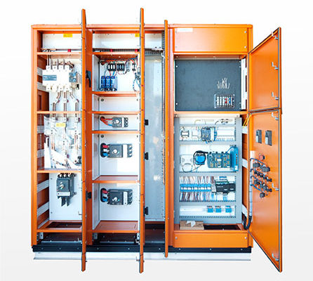
The main parts of a switchboard include:

Main Incoming Feeder: This is where the primary power supply enters the switchboard. It usually connects to the main switch or circuit breaker (Service Circuit Breaker) that controls the entire switchboard’s power supply.

Main Switch/Service Circuit Breaker: This component allows the operator to disconnect power from the entire switchboard. It serves as a safety mechanism during maintenance or emergencies.

Busbars: Busbars are conductive bars or strips within the switchboard that distribute electrical power to various branch circuits. They carry the electrical current from the main feeder to the individual circuit breakers or switches.

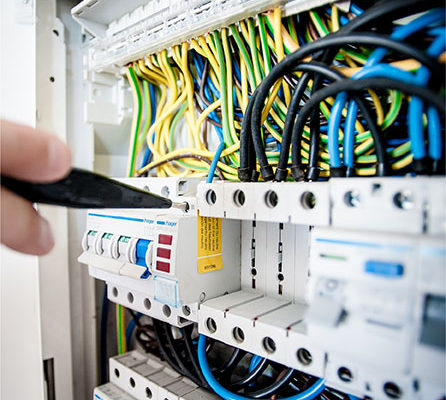
Circuit Breakers/Switches: These devices control the flow of electricity to individual circuits or loads. Circuit breakers protect circuits from overloads or short circuits by interrupting the current flow when necessary. Switches, on the other handsimply turn circuits on or off without protection against faults.

Distribution Panels: These panels contain multiple circuit breakers or switches arranged in rows and columns. Each breaker or switch corresponds to a specific electrical circuit or load within the building or facility.

Metering Devices: Some switchboards include meters for monitoring electrical parameters such as voltage, current, and power consumption. These meters provide valuable data for energy management and troubleshooting.

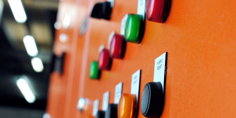
Control Components: These components include control switches, indicators, and relays that allow operators to monitor and control the switchboard’s functions. They may also include alarm systems for detecting faults or abnormalities.

Enclosure: The switchboard is normally in a protective enclosure made of metal or other durable materials. The enclosure provides insulation, protection against environmental factors, and safety for personnel working near the switchboard.

Accessories: Various accessories can be incorporated depending on the switchboard’s specific application. These can include surge protectors, arc flash protection relays, wiring ducts, cable ways, rain hoods/roofs, sun shields, vents/fans, cubicles to incorporate control equipment and labelling for identifying circuits.

These main parts work together to ensure the safe and efficient distribution of electricity within a building, facility, or industrial setting. Switchboards can vary in complexity and size based on the scale of the electrical system they serve, ranging from small residential distribution panels to large industrial switchboards for complex power distribution networks.

power system analysis

How Long Does It Take To Make A Switchboard?

The timeframe to manufacture a switchboard can vary significantly based on several factors, including the complexity of the switchboard, customisation requirements, availability of materials, production processes, and the workload of the manufacturing facility. Here’s a quick overview of the typical timeline involved in making a switchboard:

1.Design Phase (1-2 weeks):

Before any physical work begins, planning and designing work is essential. This phase involves assessing the electrical requirements of the building or facility, determining the optimal layout for the switchboard, customisation, compliance with safety standards and regulations, ordering materials (e.g. sheet metal), and selecting the appropriate components like circuit breakers, fuses, and meters. Depending on the complexity, the design phase can take a few days to several weeks.

2. Fabrication and Assembly (4-8 weeks):

Once the design is finalised, the fabrication and assembly stage commences. Skilled technicians and electricians work together to build the design, by cutting and assembling the metal enclosure, mounting electrical components, and wiring the switchboard according to the schematic diagram. This stage can take a few days for a smaller switchboard to several weeks for a larger, more intricate system.

 3. Testing and Quality Assurance (1-2 weeks):

Before deployment, testing and quality assurance procedures are conducted to ensure the switchboard functions flawlessly and adheres to safety standards. This phase involves conducting electrical tests, checking for potential faults or malfunctions, and verifying that all components are installed and functioning as intended. Depending on the complexity of the switchboard and the extent of testing required, this phase can take several days to a couple of weeks.

Overall, the time required to make an electrical switchboard can take approximately 12 -20 weeks, depending on the complexity of the switchboard, customisation requirements, and the production capacity of the manufacturing facility. It’s important to note that this timeline is a general estimate, and actual timelines may vary based on specific project details and circumstances.

What Is The Function Of A Switchboard?

In the realm of electrical engineering and infrastructure, the electric switchboard emerges as a fundamental component, orchestrating the flow of power with precision and reliability. From residential setups to industrial complexes, understanding the function of an electric switchboard unveils the intricate mechanisms that power our modern world.

The Core Function

  1. Power Distribution: The switchboard receives electrical power from the main supply or generator and distributes it to different circuits or loads within a building or facility. This distribution is achieved through circuit breakers or switches that control the flow of electricity to specific areas or equipment.
  2. Load Management: Electric switchboards allow for the effective management of electrical loads. By organising circuits and assigning priorities, switchboards prevent overload situations, ensuring that electrical devices receive the necessary power without compromising safety or efficiency.
  3. Fault Protection: Switchboards incorporate protective devices such as circuit breakers, fuses, and surge suppressors to safeguard against electrical faults. These devices detect abnormalities such as short circuits or overloads and interrupt the flow of electricity to prevent damage to equipment and mitigate safety risks.
  4. Metering and Monitoring: Many modern switchboards include meters and monitoring systems to track electrical consumption, voltage levels, and power quality. This data helps in monitoring energy usage, identifying inefficiencies, and optimising electrical systems for better performance and cost savings.

Applications Across Industries

  1. Residential Buildings: In homes, switchboards serve as the central point for distributing power from the utility grid or backup generators to different rooms and appliances. They ensure safe and reliable electricity supply for lighting, heating, cooling, and electronic devices.
  2. Commercial Establishments: In commercial buildings, switchboards manage power distribution to lighting, HVAC systems, computers, machinery, and other electrical loads. They enable efficient energy management, reduce downtime due to electrical issues, and ensure compliance with safety standards.
  3. Industrial Facilities: In industrial settings, switchboards play a critical role in powering heavy machinery, production lines, and industrial processes. They provide robust power distribution, fault protection, and monitoring capabilities to support uninterrupted operations and worker safety.
  4. Renewable Energy Systems: Switchboards are essential components of renewable energy systems such as solar or wind power installations. They integrate renewable energy sources with grid power, manage energy storage systems, and ensure seamless transition between different power sources.

In conclusion, the function of an electric switchboard encompasses the vital tasks of power distribution, load management, fault protection, and monitoring within electrical systems. From ensuring safe electricity supply in homes to powering complex industrial operations, switchboards are indispensable in maintaining reliable and efficient electrical infrastructure.