Switchboards are not typically designed to be waterproof. However, they are constructed to provide a level of protection against environmental elements, including moisture, dust, and debris. The degree of protection against moisture depends on the switchboard’s enclosure rating and the environment where it is installed.
Here are some key points regarding the waterproofing or moisture protection of switchboards:
Enclosure Ratings:
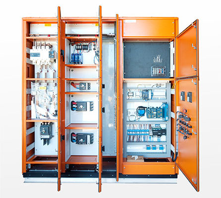
Switchboards are often in enclosures made of metal, such as steel or aluminium, or non-metallic materials like plastic or fiberglass. The enclosure’s rating, specified by standards such as the International Electrotechnical Commission (IEC) 60529 standard, and the AS 60529: 2004 (R2018), indicates the level of protection against environmental factors. Enclosure ratings such as IP (Ingress Protection) ratings, provide information about the switchboard’s resistance to moisture, dust, and other contaminants. For example, an IP65 rating means the switchboard is dust-tight and protected against water jets.
Moisture Protection Features:
Gasket Seals: Many switchboard enclosures have gasket seals around doors, panels, and openings to prevent water or moisture from entering the interior.
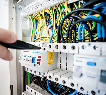
Cable Entry Seals: Seals, glands and gland plates provide a watertight seal around cable entry points to prevent water ingress along cables.
Drainage: Some switchboards may have built-in drainage systems or vents to allow any moisture that does enter the enclosure to drain out safely.
Installation Environment:
The installation environment plays a significant role in determining the moisture protection required for a switchboard. For example, switchboards installed outdoors or in damp locations may need higher waterproofing levels than switchboards installed indoors in dry environments. Hazardous or corrosive environments may require additional protective measures, such as corrosion-resistant coatings or materials.
Maintenance and Inspection:
Regular maintenance and inspection of switchboards are essential to ensure that seals, gaskets, and protective features remain intact and effective in preventing moisture ingress. Any signs of water intrusion, such as condensation inside the enclosure or water damage to components, should be promptly addressed to prevent damage and ensure electrical safety.
In conclusion, while switchboards are not inherently waterproof, they are designed with protective features and enclosure ratings to provide a certain level of moisture resistance. Proper installation, maintenance, and adherence to environmental guidelines are key to ensuring the switchboard’s protection against moisture and maintaining electrical safety.